The circuit will be built and tested with an oscilloscope and also used the data acquisition device in conjunction with LabVIEW. Recall that the ideal constant-voltage source has the property of maintaining a constant voltage regardless of the current through the supply.

Experiment 2 Dc Regulated Power Supplies Pdf Eee 311 Experiment 2 Dc Regulated Power Supplies I Introduction 1 Objectives The Objective Of This Course Hero
The objective of this experiment is to become familiar with the principles of the operation of DC regulated power supplies.
. The design and development of a simple but efficient digitally controlled regulated power supply of a variable voltage ranging from 0v to 15v with a. Single-output supply constructed in ECE 2C Fall 2000. Gain experience in making power supply performance measurements.
This 5-15V regulated power supply project is a simple power supply that has a variable DC voltage range from 5V to 15V. In this lab you will construct a regulated DC power supply to provide a low-ripple adjustable dual-output voltage in the range 9-12 VDC at 05 Amps maximum load current from a 120 V AC power outlet. Full wave circuit design has been implemented on the virtual breadboard using following specifications.
The data sheet for 5V voltage regulator LM7805 is HERE and data sheet for -5V voltage regulator LM7905 is HERE. The controlled value is held nearly constant despite variations in either load current or the voltage supplied by the power supplys energy source. The main function of the regulated power supply is to convert an unregulated alternating current AC to a steady direct current DC.
The PCB design of the Power supply will be carried out using PCB express program. It is familiarly to provide 12-volt DC power output. Then using a regulator takes ripple current from the rectifier and outputs a constant DC output.
That is it may. Up to 24 cash back The purpose of the experiment is to design a 5 V DC regulated power supply delivering up to 1A of current to the load. The selection of a regulator IC depends on your output voltage.
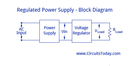
Regulated Power Supply Block Diagram. The color of the ground-wire is either green or greenyellow. It is there for your protection if the 110vac accidentally comes in contact with the supply housing case.
5 to 15V Regulated Power Supply. Conclusion The power supply that has been designed provides a good alternative to a more expensive power supply. A regulated power supply is one that controls the output voltage or current to a specific value.
EEE 311 Electronics I Laboratory Manual Exp 2 AssocProfDrTAYFUN NESİMOĞL U 1 EEE 311 Experiment 2 DC REGULATED POWER SUPPLIES I. Regulated Power Supply Vivek Menon Experiment 3. This DC output is very useful to power microchips and different ICs.
OUTPUT VOLTAGE RANGE 0 TO 12 VDC MAXIMUM OUTPUT CURRENT I MAX 200 mA PEAK TO PEAK RIPPLE at 200Ma output current 25 mV LOAD. There are many applications of power electronics such as transformer AC to DC converter or rectifier and voltage. Next thing is we need to know voltage current and power ratings of.
Do not publish elsewhere. Draw and label the schematic Figure 2 - 5 V DC regulated power supply. The finished circuit will be compared with simulated results in Multisim.
To Study the characteristics of regulated DC Power supply. Variable AC source Transformer four diode two capacitor one inductor one resistance one transistor dc voltmeter mili-ammeter variable resistor. ENS 249 Lab 4 Zener Regulated DC Power Supply Stewar Romhin This particular experiment covers the design and application of a Zener Diode regulated DC Power Supply.
It can supply current up to a 400mA to power the various circuits for your electronic projects. All computer power cords are three-prong. In this circuit the input line power supply is designed for 240VAC.
In our case we are designing for the 5V output voltage we will select the LM7805 linear regulator IC. The voltage output is varied by using the potentiometer VR1. Design and create a SPICE model of a bridge-type full-wave rectified dc power supply using a filter capacitor.
2 Identification Specification and Testing of Active Devices Diodes BJTs Low power JFETs MOSFETs Power Transistors LEDs LCDs. CIRCUITS LABORATORY Experiment 8 DC Power Supplies 81 INTRODUCTION This exercise constitutes a study of circuits that approximate an ideal constant-voltage source. The ground wire which is connected to the middle pin of the power plug is connected to the chassis.
Learn how to take steps to improve the efficiency and reliability of the power supply using worst-case design techniques. Use ORCAD to simulate your design. Regulated power supply is an electronic circuit that is designed to provide a constant dc voltage of predetermined value across load terminals irrespective of ac mains fluctuations or load variations.
Use ORCAD to simulate your design. Function generator CRO Regulated Power supply resistor diode connecting wires. This will be used to provide power to parts of the ultrasonic transceiver system that you will construct in later labs.
HP E3631A Power Supply 2. Every power supply must obtain the energy it supplies to its load as well as any energy it. Also to determine the load regulation and efficiency of the regulated power supply.
The Selection of Regulator IC. Design takes the power from the wall which has AC. Regulated Power Supply Objective.
Function generator CRO Regulated Power supply resistor diode connecting wires. REGULATED POWER SUPPLY. The student will design a regulated power supply which will meet or exceed the specifications listed below.
Experiment deals with various devices which are mainly used for design and construction of DC power supplies regulated power supplies and other devices such as CRO. To design and simulate a Full Wave Rectifier circuit. The IC Regulated power supply RPS is one kind of electronic circuit designed to provide the stable DC voltage of fixed value across load terminals irrespective of load variations.
In the power generation of most electronic and electrical circuit DC power supply is necessary. After getting the PCB printed and buying the components from Market and students will assemble the components. The load can be calculated using P V 2 R.
In this experiment you will Learn how series-pass voltage regulator circuits are designed. There is different analysis to design the circuit based on the number of output. Proper wire plug terminals should be used and PCB must be fixed with screws to metal base with required insulation.
Up to 24 cash back Experiment. To design and simulate a Full Wave Rectifier circuit. Full wave circuit design has been implemented on the virtual breadboard using following specifications.
A regulated power supply essentially consists of an ordinary power supply and a.
Regulated Power Supply Block Diagram Circuit Diagram Working

Regulated Power Supply Youtube
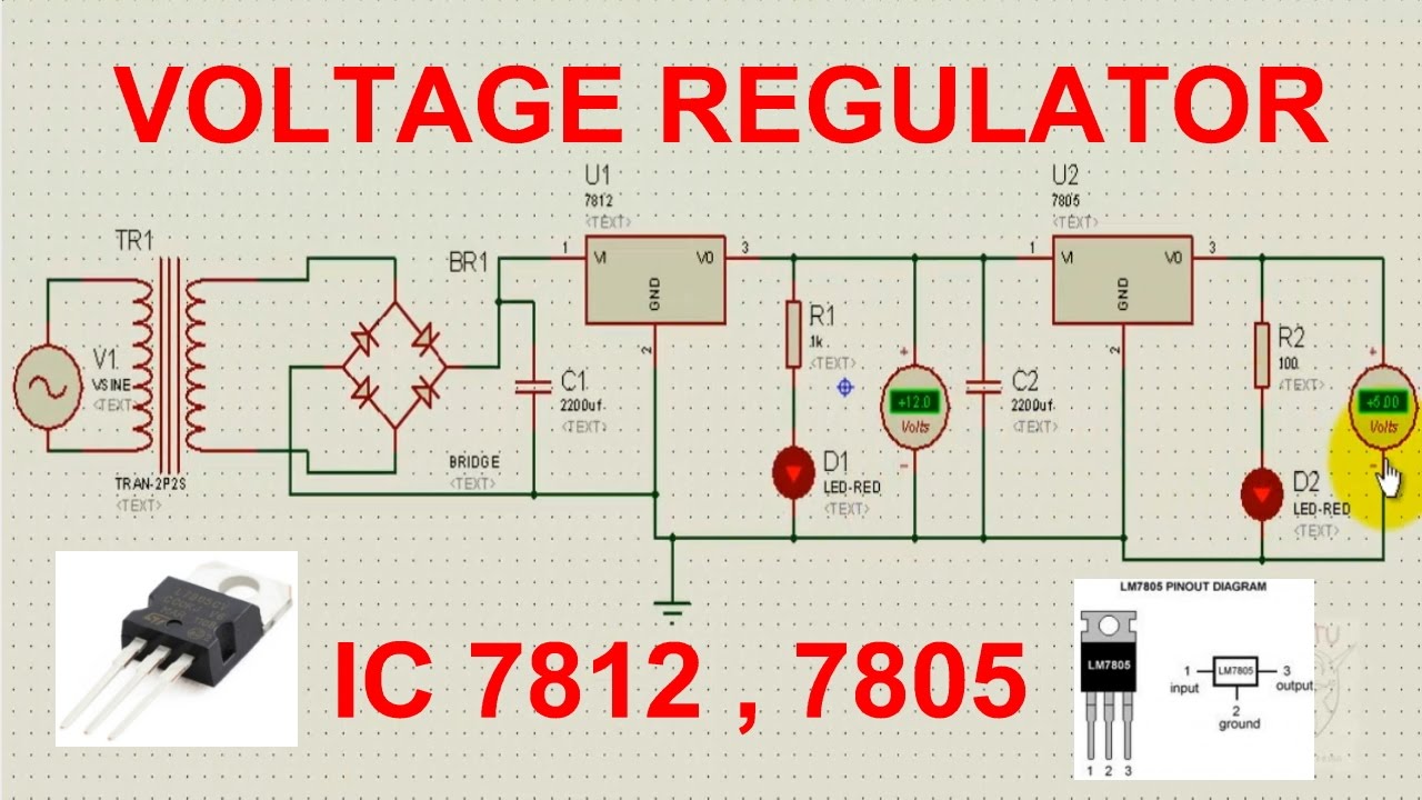
Regulated Power Supply Using Ic 7812 Youtube
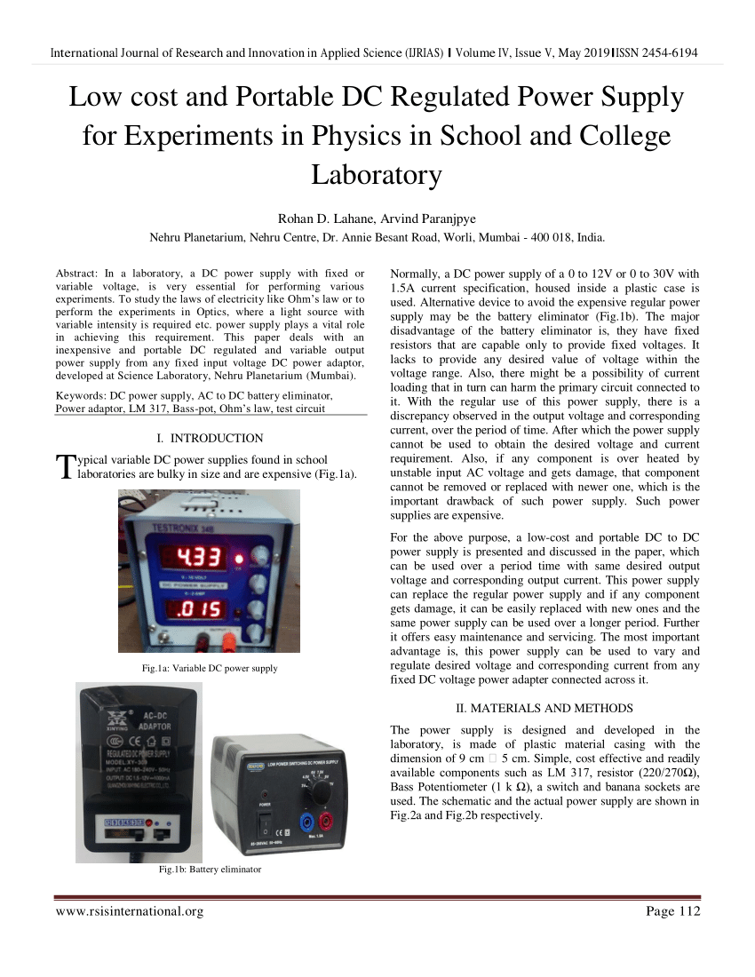
Pdf Low Cost And Portable Dc Regulated Power Supply For Experiments In Physics In School And College Laboratory
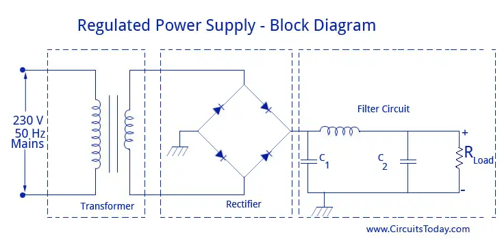
Regulated Power Supply Block Diagram Circuit Diagram Working
17ec3108 Esdw Lab Manual Student Copy Exp 1 Pcb Fabrication On Power Supply Generation With Studocu
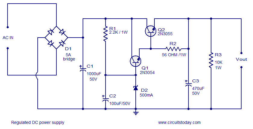
Regulated Dc Power Supply Using Transistors

Block Diagram Of A Regulated Power Supply Unit With Sinusoidal Signal Download Scientific Diagram
0 comments
Post a Comment